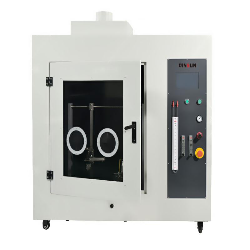
Horizontal and vertical combustion tester
The horizontal and vertical combustion tester mainly consists of a combustion chamber, a horizontal combustion device, and a vertical combustion device. It simulates the combustion conditions in a natural fire to test the burning speed and flame propagation direction of the material to evaluate the combustion performance and safety of the material.Principle
The principle of the horizontal and vertical combustion tester is based on the combustion reaction of a material within a combustion chamber. During the test, the material to be tested is first placed horizontally or vertically. Then, one end of the material is ignited, and the combustion behavior and flame propagation direction are observed. In a horizontal combustion test, the material burns horizontally, primarily evaluating its horizontal combustion performance; in a vertical combustion test, the material burns vertically, primarily evaluating its vertical combustion performance.
Instructions
I. Preliminary Preparation
1. Equipment Inspection:
Check the integrity of all components of the horizontal and vertical combustion tester, including the combustion chamber, thermocouple, sensor, gas source, and power supply.
Check that there is sufficient liquid in the U-tube.
Ensure the instrument is placed in a stable, well-ventilated laboratory, free of flammable or explosive materials.
2. Connecting the Gas Source:
Use a gas hose to connect the burner, control box, and gas tank. Check the gas line connections for leaks.
Open the gas cylinder valve, adjust the cylinder output pressure between 0.1 and 0.15 MPa, and check for airtightness.
3. Connecting the Power Supply:
Turn on the power switch and wait for the LCD touchscreen to complete the self-test.
Select the desired test standard on the touchscreen.
4. Sample Preparation:
Install the prepared standard specimen in the specimen holder, ensuring the required distance between the specimen and the combustion chamber wall.
Adjust the distance and position between the specimen and the burner nozzle. Once adjusted, do not move the specimen holder.
II. Adjusting the Flame
1. Adjusting the Blowtorch Height:
Adjust the height of the blowtorch according to the flame energy required by the test standard. For example, a 50W flame blowtorch should be screwed almost to the bottom, while a 500W flame blowtorch should be screwed close to the top of the blowtorch base.
2. Adjusting the Ignition Needle Position:
Adjust the relative position and distance between the ignition needle and the blowtorch.
3. Adjusting the Flame Size:
For a 50W flame, tighten the needle valve to a desired depth (do not tighten it completely, otherwise no gas will flow).
For a 500W flame, adjust the height of the inner and outer flames using the knobs on the flow meter.
Use a flame gauge to adjust the desired 50W or 500W flame.
III. Starting the Test
1. Ignition Preheating:
Light the blowtorch and allow the flame to preheat for 5 minutes.
2. Positioning the Sample:
Move the preheated blowtorch under the specimen, ensuring good contact between the specimen and the flame.
3. Start the Test:
If using the "Automatic" combustion mode, tap the "Test" button on the touchscreen. The program will automatically conduct the test according to standard requirements.
If using the "Manual" combustion mode, manually push and pull the blowtorch holder. Each time the flame time or interval time expires, the system will beep.
4. Observation and Recording:
During the test, observe the sample combustion and whether any sample dripping ignites the cotton underneath.
According to the test standard, record data such as the burning time, burning length, afterflame time, and afterglow time.
IV. End of Test
1. Turn Off the Flame:
After the test is complete, the program will automatically turn off the flame, or you can turn it off manually.
2. Start the Exhaust System:
Start the exhaust system to exhaust the test combustion gases from the combustion chamber.
3. Clean Up:
Open the test door and clean the sample and combustion residue to prepare for the next test.
4. Shut Down the Equipment:
Close the gas cylinder valve, ignite the flame, and allow any remaining gas in the equipment piping to burn out.
Turn off the ignition and power.
Equipment Maintenance and Care
1. Use equipment according to the manual and strictly adhere to operating procedures. Prepare carefully before startup, inspect and adjust equipment repeatedly during startup, and strictly adhere to operating specifications. Avoid overheating, overpressure, overspeed, or overload.
2. Perform meticulous maintenance, regularly check routes, and thoroughly inspect equipment. Identify problems and promptly address them, eliminating potential hazards. Ensure proper cleaning, lubrication, tightening, adjustment, and corrosion protection of equipment. Keep parts, accessories, and tools intact.
3. Understand the prevention, diagnosis, and emergency response measures for equipment failures, and maintain intact and functional safety devices.
4. Operate equipment according to schedules, perform regular replacements, and cooperate with maintenance personnel to ensure equipment is always in good condition and ready for operation. Regularly inventory spare equipment and ensure proper frost and condensation protection.
5. Carefully complete equipment operation records, defect records, and operation diaries.
6. Maintain the equipment and surroundings clean and hygienic at all times, ensuring that grooves are visible, shafts are exposed to light, the equipment is visible, and doors and windows are clean.
7. Maintain proper equipment lubrication. Regularly clean and change lubrication areas and oil tanks.